
Creating a custom speech bubble 💬
When developing iOS apps UI, it is very common to create custom controls which can be reused all across app. Custom controls allows creating very specific UI and behaviours while controling pixel perfect display. In today’s post I’m going to demonstrate how to create a custom speech-bubble which can be used in chat-like applications.
📣
We are going to create a speech-bubble view which could be used in chat-like applications. The view will look like a bubble, and we could add any content to it: a text label, an image, or any other UI element we’ll need. The view could be customized to support multiple use cases and requirements.
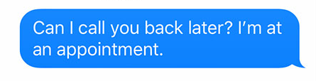
So we want something similar to iMessage chat bubbles, which looks like this:
To create the initial chat bubble drawing, we’ll use Paintcode, a great app which allows to easily creating drawing-code from any vector image. You can easily find the needed shape online, or even draw yourself in Paintcode itself. I found a vector image of a chat bubble which resembles the iMessage bubble, and this is the code Paintcode generated for me:
let bezierPath = UIBezierPath()
bezierPath.move(to: CGPoint(x: 46, y: 34))
bezierPath.addLine(to: CGPoint(x: 17, y: 34))
bezierPath.addCurve(to: CGPoint(x: 0, y: 17), controlPoint1: CGPoint(x: 7.61, y: 34), controlPoint2: CGPoint(x: 0, y: 26.39))
bezierPath.addCurve(to: CGPoint(x: 17, y: 0), controlPoint1: CGPoint(x: 0, y: 7.61), controlPoint2: CGPoint(x: 7.61, y: 0))
bezierPath.addLine(to: CGPoint(x: 47, y: 0))
bezierPath.addCurve(to: CGPoint(x: 64, y: 17), controlPoint1: CGPoint(x: 56.39, y: 0), controlPoint2: CGPoint(x: 64, y: 7.61))
bezierPath.addLine(to: CGPoint(x: 64, y: 23))
bezierPath.addCurve(to: CGPoint(x: 68, y: 34), controlPoint1: CGPoint(x: 64, y: 33), controlPoint2: CGPoint(x: 68, y: 34))
bezierPath.addLine(to: CGPoint(x: 68.05, y: 33.99))
bezierPath.addCurve(to: CGPoint(x: 56.96, y: 29.96), controlPoint1: CGPoint(x: 63.93, y: 34.43), controlPoint2: CGPoint(x: 59.84, y: 32.94))
bezierPath.addCurve(to: CGPoint(x: 46, y: 34), controlPoint1: CGPoint(x: 52, y: 34), controlPoint2: CGPoint(x: 49, y: 34))
bezierPath.close()
Creating the bubble custom view
The code generated by Paintcode is not enough, it is merely the bezier path drawing code. We still need to create our custom view, which will use it to draw the actual bubble. Let’s get to it:
@IBDesignable class BubbleView: UIView { // 1

  override init(frame: CGRect) { // 2
    super.init(frame: frame)

    commonInit()
  }

  required init?(coder: NSCoder) {
    super.init(coder: coder)

    commonInit()
  }

  private func commonInit() {
    super.backgroundColor = .clear // 3
  }

  private var bubbleColor: UIColor? { // 4
    didSet {
      setNeedsDisplay() // 5
    }
  }

  override var backgroundColor: UIColor? { // 6
    get { return bubbleColor }
    set { bubbleColor = newValue }
  }

  override func draw(_ rect: CGRect) { // 7
    let bezierPath = UIBezierPath() // 8

    bezierPath.move(to: CGPoint(x: 46, y: 34))
    bezierPath.addLine(to: CGPoint(x: 17, y: 34))
    bezierPath.addCurve(to: CGPoint(x: 0, y: 17), controlPoint1: CGPoint(x: 7.61, y: 34), controlPoint2: CGPoint(x: 0, y: 26.39))
    bezierPath.addCurve(to: CGPoint(x: 17, y: 0), controlPoint1: CGPoint(x: 0, y: 7.61), controlPoint2: CGPoint(x: 7.61, y: 0))
    bezierPath.addLine(to: CGPoint(x: 47, y: 0))
    bezierPath.addCurve(to: CGPoint(x: 64, y: 17), controlPoint1: CGPoint(x: 56.39, y: 0), controlPoint2: CGPoint(x: 64, y: 7.61))
    bezierPath.addLine(to: CGPoint(x: 64, y: 23))
    bezierPath.addCurve(to: CGPoint(x: 68, y: 34), controlPoint1: CGPoint(x: 64, y: 33), controlPoint2: CGPoint(x: 68, y: 34))
    bezierPath.addLine(to: CGPoint(x: 68.05, y: 33.99))
    bezierPath.addCurve(to: CGPoint(x: 56.96, y: 29.96), controlPoint1: CGPoint(x: 63.93, y: 34.43), controlPoint2: CGPoint(x: 59.84, y: 32.94))
    bezierPath.addCurve(to: CGPoint(x: 46, y: 34), controlPoint1: CGPoint(x: 52, y: 34), controlPoint2: CGPoint(x: 49, y: 34))
    bezierPath.close()

    backgroundColor?.setFill() // 9
    bezierPath.fill()
  }
}
OK there is a lot to take in here, let’s go over all points:
- We define a new custom view BubbleView which inherits from UIView. We mark it as @IBDesignable so interface builder will try to render it when used in storyboards/xibs.
- We override both initializers, and call a common initialization function.
- We set super background color to clear.
- We define a new var representing the bubble’s color.
- We call setNeedsDisplay when we set a new bubble color, to force the view to redraw itself.
- We override UIView backgroundColor var and use our own var. This way when clients of our custom view will change the background color, the bubble drawing will change its fill color, while the view’s default layer color will remain unchanged (clear color).
- We override draw function so it will draw the bubble.
- This is the code generated by Paintcode.
- We set the bubble’s fill color as the views background color.
So now we have a new custom view we can use! If we add a new UIView in interface builder, and set its type to BubbleView, it looks like this:
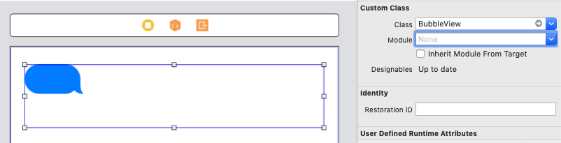
Can you see anything wrong with it? You can see that the bubble is drawn arbitrarily to the view’s actual size. Not very useful.
Dynamic view in a dynamic world
Let’s make our view more dynamic. We’ll want the bubble to be drawn on the exact view’s bounds:
  @IBInspectable var borderWidth: CGFloat = 0 { // 1
    didSet {
      setNeedsDisplay()
    }
  }

  @IBInspectable var borderColor: UIColor = .clear { // 2
    didSet {
      setNeedsDisplay()
    }
  }

  override func draw(_ rect: CGRect) {
    let bezierPath = UIBezierPath()
    bezierPath.lineWidth = borderWidth // 3

    let bottom = rect.height - borderWidth // 4
    let right = rect.width - borderWidth
    let top = borderWidth
    let left = borderWidth

    bezierPath.move(to: CGPoint(x: right - 22, y: bottom)) // 5
    bezierPath.addLine(to: CGPoint(x: 17 + borderWidth, y: bottom))
    bezierPath.addCurve(to: CGPoint(x: left, y: bottom - 18), controlPoint1: CGPoint(x: 7.61 + borderWidth, y: bottom), controlPoint2: CGPoint(x: left, y: bottom - 7.61))
    bezierPath.addLine(to: CGPoint(x: left, y: 17 + borderWidth))
    bezierPath.addCurve(to: CGPoint(x: 17 + borderWidth, y: top), controlPoint1: CGPoint(x: left, y: 7.61 + borderWidth), controlPoint2: CGPoint(x: 7.61 + borderWidth, y: top))
    bezierPath.addLine(to: CGPoint(x: right - 21, y: top))
    bezierPath.addCurve(to: CGPoint(x: right - 4, y: 17 + borderWidth), controlPoint1: CGPoint(x: right - 11.61, y: top), controlPoint2: CGPoint(x: right - 4, y: 7.61 + borderWidth))
    bezierPath.addLine(to: CGPoint(x: right - 4, y: bottom - 11))
    bezierPath.addCurve(to: CGPoint(x: right, y: bottom), controlPoint1: CGPoint(x: right - 4, y: bottom - 1), controlPoint2: CGPoint(x: right, y: bottom))
    bezierPath.addLine(to: CGPoint(x: right + 0.05, y: bottom - 0.01))
    bezierPath.addCurve(to: CGPoint(x: right - 11.04, y: bottom - 4.04), controlPoint1: CGPoint(x: right - 4.07, y: bottom + 0.43), controlPoint2: CGPoint(x: right - 8.16, y: bottom - 1.06))
    bezierPath.addCurve(to: CGPoint(x: right - 22, y: bottom), controlPoint1: CGPoint(x: right - 16, y: bottom), controlPoint2: CGPoint(x: right - 19, y: bottom))
    bezierPath.close()

    backgroundColor?.setFill()
    borderColor.setStroke() // 6
    bezierPath.fill()
    bezierPath.stroke()
  }
- We add a new var to set the width of the bubble’s border. We mark it as @IBInspectable so we could change its value from the attributes inspector in interface builder.
- We do the same for border color.
- We set the bezier path line width to the value of borderWidth.
- We set 4 vars respresenting all of the view’s anchors. These values will be used for drawing the bezier path.
- This is the trickiest part: We have to go over the code from previous state, and change it to be dynamic rather than constant. If you look into the bezier code, you could identify how it is drawn based on a constant frame. We need to replace the constant values with values based on the anchors we defined on step 4. This way, every time the view’s bounds will change, so will the bubble drawing.
- Since we introduced a border for the bubble, we need to set a stroke color for the bezier path.
If we did it right, our bubble view should look like this in interface builder:
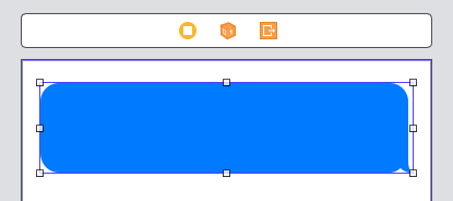
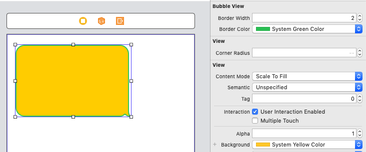
We can now play with all the attributes we defined earlier and see instantly the result:
Pretty cool!
Pointing to the right direction
One last thing, chat bubbles often points towards left or right, depending on the message source, either it’s the user himself, or it’s remote users who participate in the chat. Let’s make our bubble view support it:
  enum ArrowDirection: String { // 1
    case left = "left"
    case right = "right"
  }

  var arrowDirection: ArrowDirection = .right { // 2
    didSet {
      setNeedsDisplay()
    }
  }

  @IBInspectable var arrowDirectionIB: String { // 3
    get {
      return arrowDirection.rawValue
    }
    set {
      if let direction = ArrowDirection(rawValue: newValue) {
        arrowDirection = direction
      }
    }
  }

  override func draw(_ rect: CGRect) {
    // ... unchanged

    if arrowDirection == .right { // 4
      // ... unchanged
    } else {
      bezierPath.move(to: CGPoint(x: 22 + borderWidth, y: bottom)) // 5
      bezierPath.addLine(to: CGPoint(x: right - 17, y: bottom))
      bezierPath.addCurve(to: CGPoint(x: right, y: bottom - 17), controlPoint1: CGPoint(x: right - 7.61, y: bottom), controlPoint2: CGPoint(x: right, y: bottom - 7.61))
      bezierPath.addLine(to: CGPoint(x: right, y: 17 + borderWidth))
      bezierPath.addCurve(to: CGPoint(x: right - 17, y: top), controlPoint1: CGPoint(x: right, y: 7.61 + borderWidth), controlPoint2: CGPoint(x: right - 7.61, y: top))
      bezierPath.addLine(to: CGPoint(x: 21 + borderWidth, y: top))
      bezierPath.addCurve(to: CGPoint(x: 4 + borderWidth, y: 17 + borderWidth), controlPoint1: CGPoint(x: 11.61 + borderWidth, y: top), controlPoint2: CGPoint(x: borderWidth + 4, y: 7.61 + borderWidth))
      bezierPath.addLine(to: CGPoint(x: borderWidth + 4, y: bottom - 11))
      bezierPath.addCurve(to: CGPoint(x: borderWidth, y: bottom), controlPoint1: CGPoint(x: borderWidth + 4, y: bottom - 1), controlPoint2: CGPoint(x: borderWidth, y: bottom))
      bezierPath.addLine(to: CGPoint(x: borderWidth - 0.05, y: bottom - 0.01))
      bezierPath.addCurve(to: CGPoint(x: borderWidth + 11.04, y: bottom - 4.04), controlPoint1: CGPoint(x: borderWidth + 4.07, y: bottom + 0.43), controlPoint2: CGPoint(x: borderWidth + 8.16, y: bottom - 1.06))
      bezierPath.addCurve(to: CGPoint(x: borderWidth + 22, y: bottom), controlPoint1: CGPoint(x: borderWidth + 16, y: bottom), controlPoint2: CGPoint(x: borderWidth + 19, y: bottom))
    }

    // ... unchanged
  }
- We define a new enum representing arrow direction.
- We add a new var to hold the desired arrow direction.
- We define an @IBInspectable wrapper for the arrow direction var, to allow editing via interface builder.
- In case the desired arrow direction is .right, our code from previous state is valid.
- This is the mirror case of the default drawing. The code just mirrors all X axis acnhors and margins.
And now we can set the arrow to point left, and see it immediatley in interface builder:
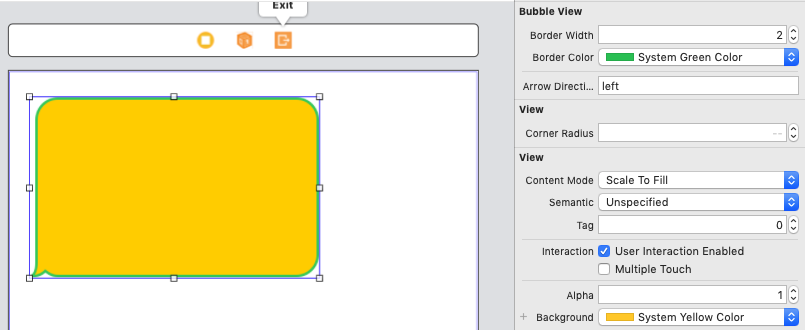
Sweet.
Conclusion
We learnt how to create a fully functional custom control which includes advanced drawing. We learnt how to add IBInspectable properties to custom views, and be able to instantly see how changing them affects the view. We also learnt about converting static views into dynamic robust views. 🎊